Programming 3
University of Alicante, 2025–2026
Third Programming Assignment
Implementation inheritance
| Relative weight of this assignment in the practice grade: 15%. |
An input/output system
Base project
Download the Eclipse base project for this assignment, which already contains some classes and unit tests. Import it as a Java project in Eclipse
Introduction
In this assignment we introduce the use of implementation inheritance, which we have studied in unit 4.
In the es.ua.dlsi.prog3.p3.lowlevel package we have been
provided with a low-level library for communication between non-specific
input/output devices (InputDevice and
OutputDevice ) that communicate through a channel
(Channel). However, we want the client code provided in the
source code package es.ua.dlsi.prog3.p3.client to work with
objects representing specific devices such as a keyboard, a display, a
mouse, etc.. To do this we have to design and implement the classes of
the es.ua.dlsi.prog3.p3.highlevel package, which are the
ones used by the client code to define input/output devices.
The Eclipse project already contains some classes from the lowlevel package and the client package mentioned above, as well as some unit tests. At the beginning you will have compilation errors in the client package, this is normal, as it depends on the highlevel package; they will disappear as you implement the latter.
When doing your implementation, keep in mind the different levels of visibility of each element (attributes and methods) as represented in the UML diagram. This is especially important when working with inheritance.
Here is the UML diagram of these classes (omitting the
es.ua.dlsi.prog3.p3.client package):


In this UML classes are represented without inheritance
relationships. You must design the necessary inheritance relationships
so that the classes in package
es.ua.dlsi.prog3.p3.highlevel, along with classes
InputDevice and OutputDevice in package
es.ua.dlsi.prog3.p3.lowlevel are actually part of a single
class hierarchy whose root will be, as explained below,
IODevice.
The way to communicate between two devices is to create a channel common to both devices using an instance of the Channel class:
Keyboard keyboard = new Keyboard();

LinePrinter printer = new LinePrinter();

Channel channel = new Channel(keyboard, printer);
and from then on, anything sent to the channel from the input device (keyboard) can be read by the output device (printer):
keyboard.put((char)4);
for (char c='A'; c<'D'; c++) keyboard.put(c);

String line = printer.printLine(); // returns the string "ABCD"
Each output device has a very simple communications protocol that
defines what must be sent to the channel in order for the device to read
it. This is detailed below, in the description of the output devices in
the es.ua.dlsi.prog3.p3.highlevel package.
Package es.ua.dlsi.prog3.p3.lowlevel
The classes Channel and IODevice in this
package are provided with their implementation. You should NOT modify
them. As you read this description, refer to the source code of the
package to better understand how its classes work internally.
As you can see in the UML diagram, a Channel is created
from two IODevice devices. The two arguments to the
constructor of Channel are, in that order, the input device
and the output device. The channel is constructed with a buffer
where the information sent from the input device is stored, which will
then be read by the output device. These devices will use the
input(byte) and output() methods of
Channel to send and receive data from the channel byte by
byte.
Class Channel
We have a constructor and three public methods that we can be used to query the channel status:
Channel(IODevice, IODevice) Creates a channel and associates the devices passed as parameters to this channel. The first argument is the input device and the second argument is the output device. This constructor allocates memory for a buffer of the size specified by the output device, so whenever we refer to the buffer of an output device, we are actually referring to the buffer of the channel associated with the device.
isFull() : indicates if the channel is full (and therefore no more data can be written to it).
hasData() : indicates that there are bytes stored in the channel pending to be read.
getBufferSize() : returns the maximum capacity of the channel (the size of its buffer), regardless of whether it contains information available for reading or not.
In addition, Channel has three other methods that
devices can use:
- input(byte) : sends a byte to the channel. It throws the exception BufferOverflowException if the channel buffer is already full.
- output() : reads a byte from the channel. It throws the exception BufferUnderflowException if the channel buffer contains no data to read.
- resetBuffer(int bufferSize) : initialises the channel buffer to the size specified by bufferSize. Any data previously contained in the channel buffer shall be lost. It throws the exception IllegalArgumentException if the argument is not greater than zero.
Class IODevice
IODevice devices are connected to a channel by the
Channel constructor. Two constructors are available to
create a device: the default constructor is used to create an input
device, while the overloaded constructor is used to create output
devices. The latter needs as a parameter the size of the buffer that the
channel through which information will be sent to the device must have.
The Channel constructor will query this information to
create the channel.
The IODevice methods that can be used to implement the
high-level devices are:
- getChannel() : returns the channel associated with this device. It throws IllegalStateException if the device has no associated channel.
- setChannel(Channel) : associates the device with the channel passed as an argument. It throws NullPointerException if the argument is null.
- getBufferSize() :returns the buffer size of the channel associated with this device.
Classes InputDevice and OutputDevice
These classes, which you have to implement, represent, respectively, a non-specific input device and a non-specific output device.
InputDevice- InputDevice() creates a new input device.
- sendToChannel(byte) : sends a byte to the associated channel.
- put(byte[]) allows sending an array of bytes to the associated channel.
Both sendToChannel() and put() throw the standard exceptions IllegalStateException if the device has no associated channel and BufferOverflowException if the channel is already full or becomes full while sending data.
OutputDeviceOutputDevice(int) : creates an output device. The buffer size of the device is specified in the constructor parameter.
receiveFromChannel() : reads a byte from the associated channel. It throws the standard exception IllegalStateException if there is no channel associated with this device, and BufferUnderflowException if there is no data in the channel.
get(int num_bytes) : reads at most num_bytes from the associated channel. It returns an array of bytes with a size equal to the number of bytes read (which may be zero if the channel contains no data).
- It throws the standard exception IllegalStateException if the device has no associated channel.
- If the num_bytes parameter is not greater than zero and less than or equal to the buffer size of this device, it throws the standard exception IllegalArgumentException.
readStoredString() (This method is given already implemented; see source code in the base project). It reads a string sent to the channel and returns it as an object of type String. The method assumes that a character string with the following format is in the channel buffer: the first byte indicates the number of bytes in the buffer, which represent printable ASCII characters. For example, if the channel contains the string “PROG3”, it will be stored in its buffer as follows:
| 5 | 80 | 82 | 79 | 71 | 51 |.- It returns the string read, or the empty string if there is no data in the channel.
- It throws the standard exception IllegalStateException if the device has no associated channel.
- It throws BufferUnderflowException if the channel is emptied before the entire string can be read, i.e. if the data in the channel is not in the correct format.
Package es.ua.dlsi.prog3.p3.highlevel
In this package we need to create a class hierarchy that allows
defining specific input and output devices, based on
InputDevice and OutputDevice. It should be
possible to use them as in the client code example in the introduction,
or the one you can find in the es.ua.dlsi.prog3.p3.client
package.
You must design the inheritance hierarchy that the classes in this
package form along with InputDevice and
OutputDevice. They are all subclasses of
es.ua.dlsi.prog3.p3.lowlevel.IODevice, directly or
indirectly. Organise classes based on the concepts they represent. More
specific concepts will inherit from more general ones. If your class
hierarchy is not well designed, oracle tests will not compile
correctly.
IMPORTANT: Just because a method throws an exception does not imply that that method must make the appropriate verifications, it may use other methods that already do so.
Input devices
The classes Keyboard and Mouse represent
specific input devices. They simulate a keyboard and a mouse,
respectively. Keyboard allows sending characters one at a
time, while Mouse simulates sending the current position of
a mouse cursor on the screen.
Keyboard:- Keyboard() creates a keyboard for sending characters.
- put(char) sends a character to the associated channel. It throws the standard exception IllegalStateException if the device has no associated channel and BufferOverflowException if the channel is already full.
Mouse:- Mouse() creates a mouse to send 2D coordinates of the cursor position on the screen.
- put(byte x, byte y) sends two bytes representing a 2D coordinate: the ‘x’ byte first, followed by the ‘y’ byte. It throws the standard exception IllegalStateException if the device has no associated channel and BufferOverflowException if the channel is already full.
Output devices
The classes Display, LinePrinter represent
different types of specific output devices. They simulate, respectively,
a display, and a printer that prints line-by-line characters.
LinePrinterThis device expects a string of characters in its buffer in the following format: the first byte indicates the number of bytes that follow it in the buffer, which represent printable ASCII characters (see OutputDevice.readStoredString() method).- LinePrinter() creates a printer with a buffer size indicated by the constant LinePrinter.MAX_LINE_LENGTH plus one.
- printLine() returns a String containing
the string read from the buffer.
- It throws the standard exception IllegalStateException if the device has no associated channel.
- It throws the checked user exception
NoLineForPrintingExceptionif the buffer is empty. This exception shall be defined in thees.ua.dlsi.prog3.p3.highlevel.exceptionssubpackage and shall not receive any parameters in its constructor.
Displaysimulates a square screen of NxN pixels in black and white, represented by an array of NxN bytes. The size N is stored in thepixel_rowsattribute, which indicates the number of rows (and columns) in the matrix. A zero in the matrix represents a ‘blank’ or non-activated pixel. Any other number represents a ‘black’ or activated pixel. Note that the byte matrix represents the contents of a graphical display where the X-axis is the horizontal axis, and the Y-axis is the vertical axis, so an (x,y) coordinate corresponds to the pixel in the ‘x’ column and ‘y’ row of the matrix. The four corners of a screen of size NxN therefore correspond to these coordinates:top left corner: (0,0)
upper right corner: (N-1,0)
bottom left corner: (0,N-1)
bottom right corner: (N-1,N-1)
Display(int N) creates a display with N rows x N columns of pixels. The channel associated with this device will have a buffer of size NxN*2, since two bytes are needed for each pixel and we want the buffer to eventually hold the coordinates of all pixels.
getDisplaySize() : returns the number of rows (or columns) of this display.
refresh() This method expects to find in the channel coordinates of pixels to be activated on the screen. It must therefore read these from the channel while there is data left in it and activate the pixels corresponding to them, setting the corresponding positions of the display array to a non-zero value. The channel will therefore contain pairs of bytes (x,y) representing coordinates for pixels on this screen. Note that it does not have to contain as many coordinates as there are pixels on the screen, there may be less or even none. If the channel contains no data, this method will not modify the display matrix.
- The method returns a defensive copy of the
displayattribute. - If the device has no associated channel, the standard IllegalStateException shall be thrown.
- If, when trying to read a coordinate from the channel, there are not enough bytes in the channel (at least two), the standard exception BufferUnderflowException is thrown.
- The (x,y) coordinates read from the buffer must correspond to some
pixel on the screen, i.e.:
(0 <= x < N) and (0 <= y < N). Otherwise, the standard exception IndexOutOfBoundsException shall be thrown with an appropriate message.
- The method returns a defensive copy of the
clear() completely clears the screen, disabling all its pixels.
Package es.ua.dlsi.prog3.p3.client
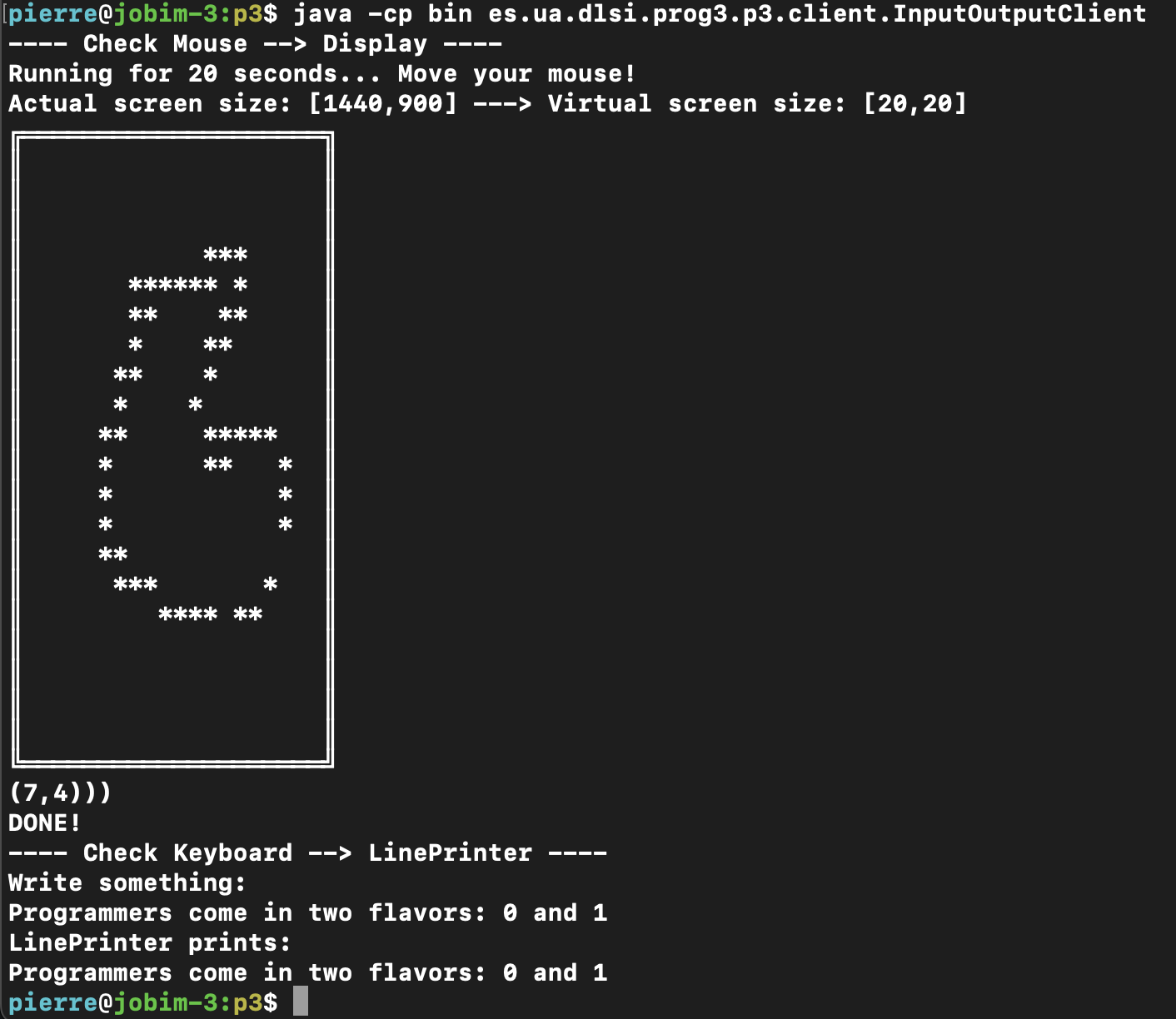
The InputOutputClient class, which is already
implemented, uses the devices defined in the
es.ua.dlsi.prog3.p3.highlevel package to demonstrate its
operation. Specifically, it connects a Mouse to a
Display, tracking the movement of the mouse for 20 seconds
and drawing the contents of the Display on an ASCII screen on
the console. Then it connects a Keyboard with a
LinePrinter.
In order to run this program, you need to run it from a terminal and on a machine with a single screen (otherwise it will give errors). Open a terminal and go to the root directory of the Eclipse project for this assignment. There, run the program like this:
$ java -cp bin es.ua.dlsi.prog3.p3.client.InputOutputClientBelow you can see an example of the output of this program:
Here you can find a video showing the program in action.
Unit tests
We provide unit tests in the test/ folder of the base
project that check for proper class behaviour. It is important that you
understand what is tested and how it is done.
Documentation
This section will not be done in the control.
You must include in the source files all necessary comments in javadoc format. These comments must be defined at least for:
- Files: you must include name and id number (DNI, NIE, etc.) of the authors using the annotation @author.
- Classes: purpose of the class: at least 3 lines.
- Operations/methods: 1 line for trivial functions, and a minimum of 2 lines, input parameters, output parameters and dependent functions for more complex operations.
- Attributes: purpose of each attribute: at least 1 line.
You can use a non-javadoc comment when necessary.
It is not necessary to generate in HTML the javadoc documentation.
Minimal requirements for grading your assignment
- Your program must run with no errors.
- Unless otherwise stated, your program must not emit any kind of message or text through the standard output or standard error streams. Also avoid error output messages.
- The format of the name of all properties (public, protected and private) of classes must be strictly respected, both in terms of visibility scope and in terms of their name. Make sure that you respect the distinction between class and instance attributes, as well as the uppercase and lowercase letters in the identifiers.
- Your code must be conveniently documented and significant content has to be obtained after running the javadoc tool.
Submission of the assignment
The practice is delivered on the DLSI practice server.
You must upload a compressed file with your source code (only .java files). In a terminal, place yourself in the ‘src’ directory of your Eclipse project and enter the command
tar czvf prog3-p3.tgz *
This will compress all the code in src/, including those classes that were already implemented. This is correct and should be delivered as is.
Upload this prog3-p3.tgz file to the practice server.
Follow the instructions on the page to log in and upload your work.
This delivery is only used to evaluate the documentation and to obtain the result of the oracle.
Grading
Testing of your assignment will be done automatically. This means that your program must strictly conform to the input and output formats given in this document, as well as to the public interfaces of all the classes: do not change the method signatures (name of the method, number, type and order of arguments, and data type returned) or their behaviour. So, for example, the Clase(int,int) method must have exactly two arguments of type int.
You can find more information about the grading of programming assignments in the subject description sheet.
In addition to the automatic grading, a plagiarism detection application will be used.
The applicable regulations of the University of Alicante Polytechnic School in the event of plagiarism are indicated below:
“Theoretical/practical work must be original. The detection of copy or plagiarism will suppose the qualification of”0” in the corresponding assignment. The corresponding Department and the University of Alicante Polytechnic School will be informed about the incident. Repeated conduct in this or any other subject will result in notification of the offences committed to the pertinent vice canchellor’s office so that they study the case and punish it in accordance with the legislation in force”.
Clarifications
- Although not recommended, you can add private attributes and methods to the classes. Notice, however, that you must implement ALL the methods indicated in this document and make sure that they work as expected, even if they are never called in your implementation.
- Any additional remark will be published in this page. It is recommended that you use this page as the primary source of the instructions.
- We advise you to implement the classes in the order that they appear in this statement.
- When sending data of type
int,char…to the channel, cast them to(byte). - As you implement classes, you should test that unit tests for that class work correctly.
- Remember to use Eclipse’s coverage analysis to detect those parts of your code that the tests are not checking.
Display: the(x,y)coordinates read from the channel indicate the horizontal and vertical axis of the ‘screen’, respectively, that is, with a(x,y)coordinate, we are referring to the components of the display array in this way:display[y][x].- Since the objective of this assignment is to learn to use inheritance, when implementing subclasses you must take advantage of the behavior, in both normal and error handling conditions, that is already implemented in the superclasses. If you implement inheritance between classes correctly, you will be able to implement many of the subclass methods in one or two lines.
